SOFTWARE
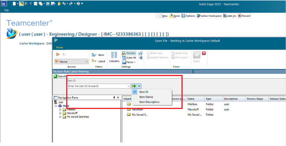

Extend Solid Edge & Teamcenter Search Capabilities
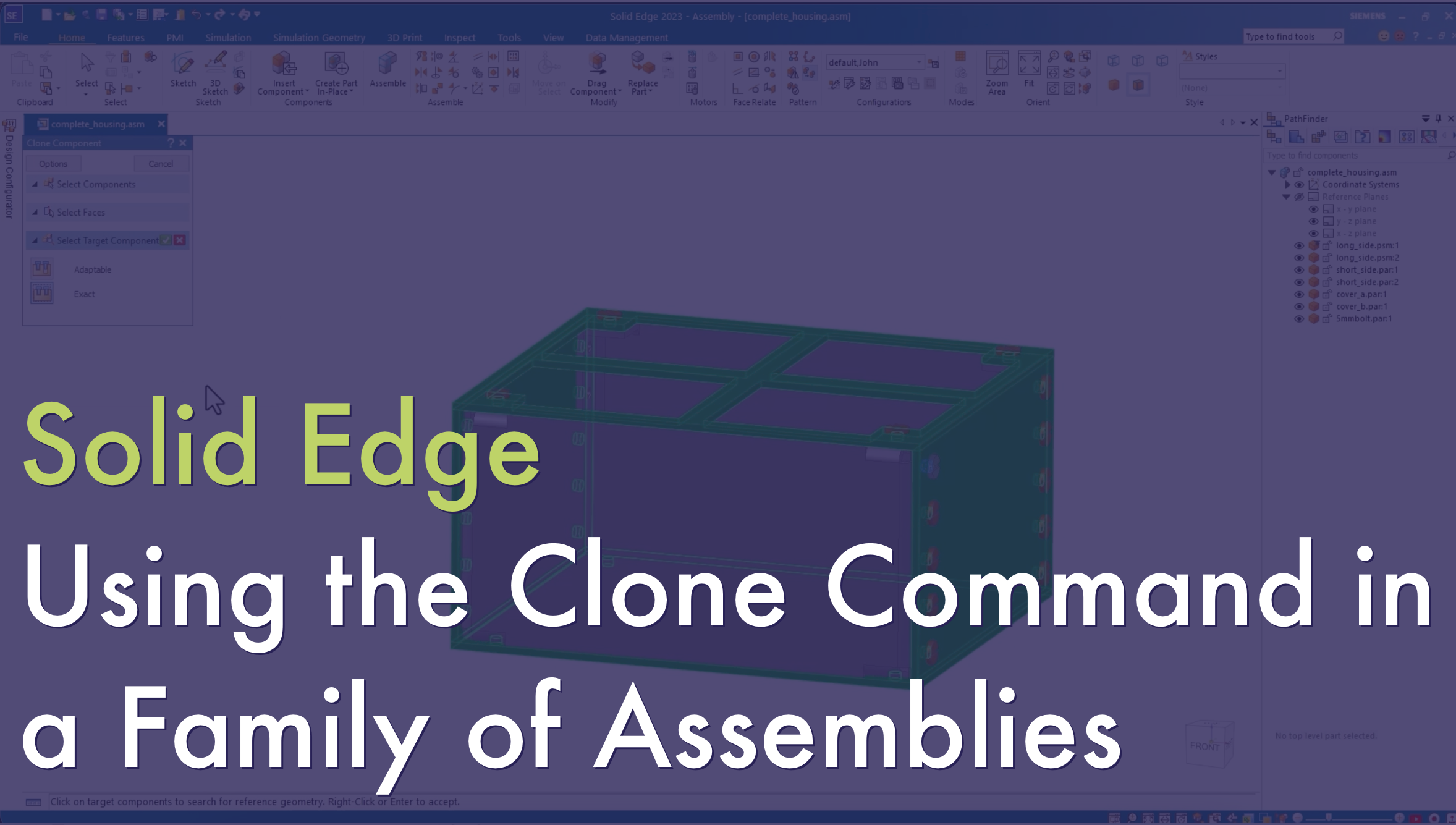
Read MoreUsing the Clone Command with a Family of Assemblies
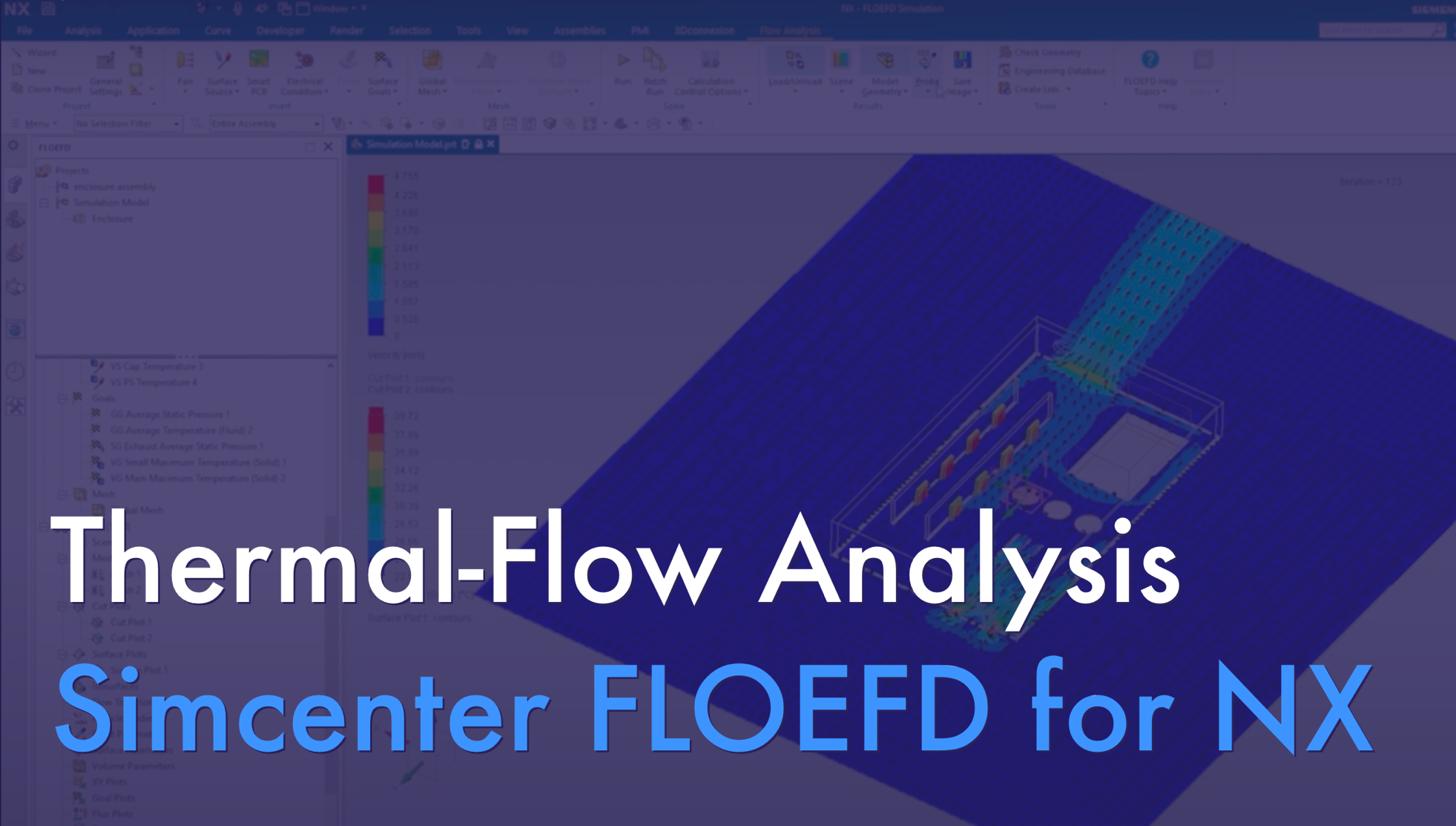
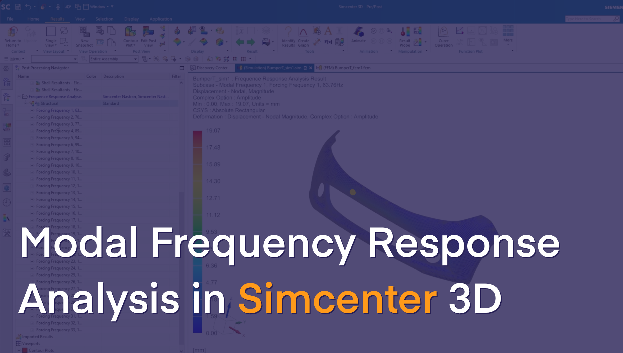
Read MoreLearn how to set up a Frequency Response Analysis in Simcenter 3D to assess a vibrating body's response and avoid system failure.
Read MoreMaximize Your Markforged 3D Printer's Potential: Unlock Efficiency and Innovation
Read More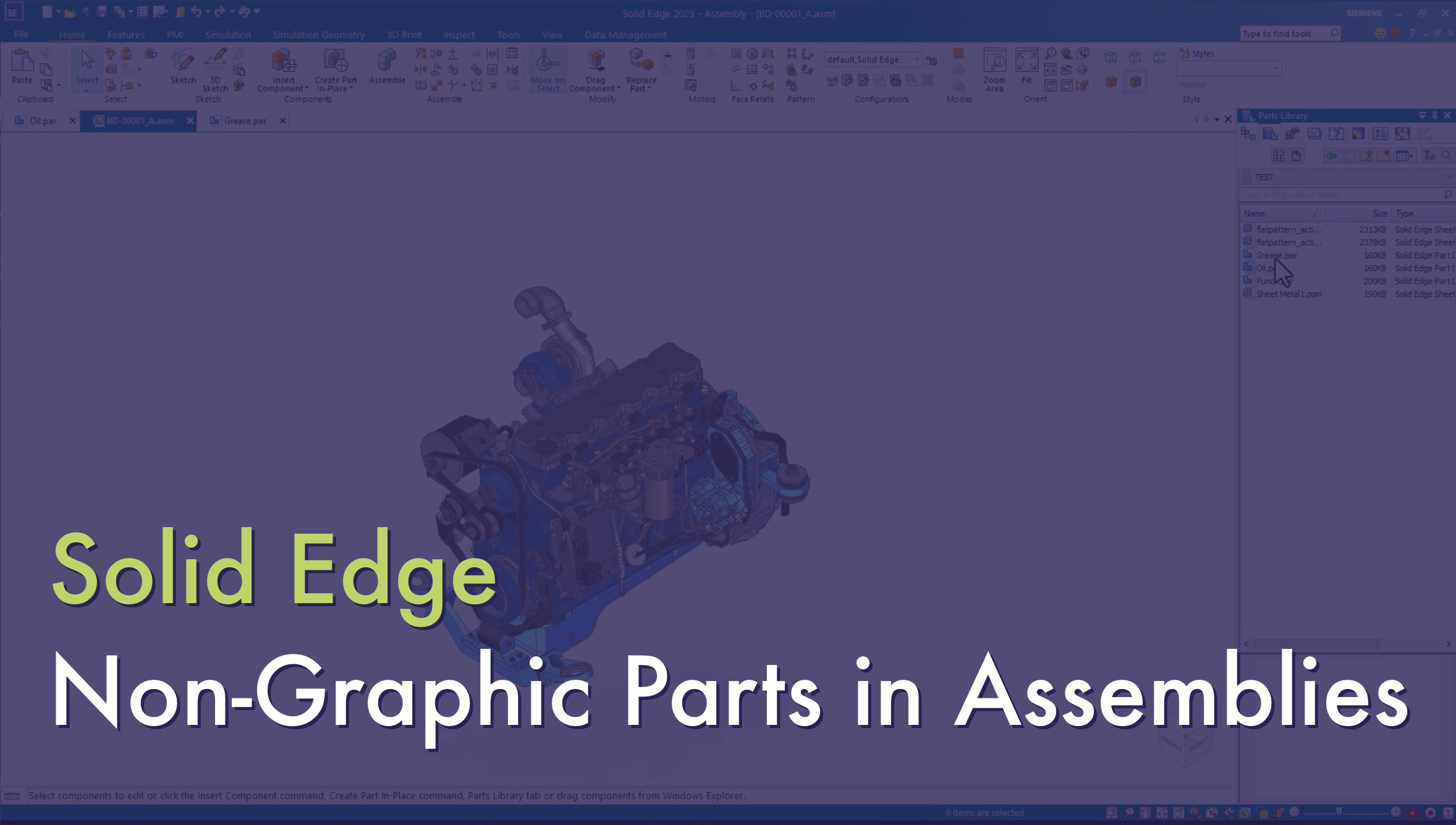
Sharing with you how to create and place non-graphic parts in assemblies.
Read More
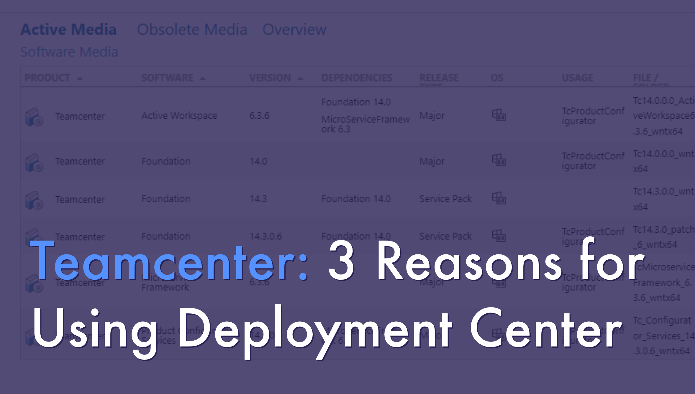
The following example outlines a supported procedure using Teamcenter Access Manager to allow a group of users to access only specific documents that have been reviewed and released to production.
Read More


Designfusion is the largest dedicated solution provider of Siemens PLM software in North America. With an expert support team and a decade of history in the industry designfusion is the #1 choice for companies looking to best enhance their software acquisition.
305 Milner Ave, Suite 308,
Toronto, Ontario, M1B 3V4
Canada
Phone: 416 267-5542
Toll Free: 1-888-567-3933
2734, rue Étienne Lenoir Laval, Quebec. H7R 0A3
Canada
Phone: 514-761-5682
Toll Free: 1-866-534-5682
565, rue Shefford, Suite 1
Bromont, Québec, J2L 1C2
Canada
Phone: 450-534-5682
Toll Free: 1-866-534-5682
1400 E Touhy Ave, Suite 477
Des Plaines, IL 60018
USA
Phone: 847-439-0555
Toll Free: 1-866-921-1830
3477 Corporate Parkway, Suite
104 Center Valley, PA 18034
USA
Toll Free: 1-866-921-1830
151 Castleberry Ct. Ste.
CMilford, OH 45150
USA
Toll Free: 1-866-921-1830
60 Scarsdale Rd, Unit 119
Toronto, Ontario, M3B 2R7
Canada
1919, Boulevard Lionel-Bertrand Suite 101, Boisbriand,
QC J7H 1N8, Canada